I have been into electronics, almost as long as I can remember walking around. Well, not quite that early on, but electronics has been a big part of my career and life – since before I was a teen. We’ll be generous and say 40+ years.
Most people will tell you that Aquaponics is a combination of Hydroponics – growing plants in a soil-less environment with Aquatics – fish, aquariums or fish farming. For me, the ‘onics’ also includes electronics.
My first major Aquaponics project was the Tent and barrels. I began the electronics part using the Arduino micro-controller platform, xBee wireless radios, and my existing IT infrastructure of Microsoft SQL servers to create a multi-node, wireless electronic monitoring system for my garden and tanks. I created a small wireless network that monitored ‘The Ponds’ and ‘The Barrels’.
As this is an introductory article, I won’t go into heavy detail, but suffice it to say, future posts will cover my design ideas, implementation, lessons learned and ideas for the future.
2016-03-11 Update
After much angst and re-design, I have my backyard monitoring system back on line. If you have read some of my other posts, my current backyard aquaponics configuration consists of two fish tanks (the box tank 200+ gallons and the refrigerator tank 80+ gallons) and one growbed (the buckets).
My current monitoring configuration is temperature (ambient air and three liquid), humidity and pressure. Upcoming sensors will monitor water level and ambient light. This is hosted locally on the monitor node hardware and can be viewed through wireless on my internal network – I am not planning on making this publicly accessible. I am planning on programming alarm levels so I can be alerted to important condition changes. For instance, the refrigerator tank has a fast evaporation level and also being a smaller system has to be topped up every three days or so. It would be nice to get a text to my cell phone telling me if the water level is too low. A burned out pump costs $40 to replace and that has happened once in the last couple of years and there have been plenty of close calls.
As a side note, if you are thinking an aquaponics system is low maintenance, you had better consider a change of thinking. There are many more moving parts and things that can go wrong versus a traditional raised bed garden. I just think this is way more fun.
Hardware: Raspberry Pi 3 (yes, brand new) running Raspbian Jessie, 8GB SD card. Dry sensor is a BME280 I2C sensor and the water temps are read using three DS18S20B sensors in waterproof stainless steel housings with 6′ cables to the sensor box.
Software: I use Apache with PHP for the web front end, Python scripts running on Cron jobs every five minutes to poll the sensors and then storing the data into a MySQL database. I utilize KoolPHP scripts to help with the charting and database editing needs. I can also see the status of the sensors and can see if any are off-line.
I’ve created seven different reports with graphs that allow me to select a data/time range for the different sensors. Below is a snapshot of a chart of the last 20 hours showing ambient air temp, and the three liquid temperatures.
I decided I wanted to monitor the bucket water temperature as its own data stream because although it is being fed from the refrigerator tank, it does sit dormant during the times that the pump is off. As you can see from the orange line on the chart, I can get valuable data from this reading.
Another design change – originally, I purchased and built a 3D printer with the intent of creating custom project boxes. Disappointingly, though, the boxes did not prove to be robust enough to withstand constant installation/de-installation. I decided to re-box the controller and sensor modules in SMT electrical boxes that are substantially stronger and can be made completely weatherproof if needed. Currently, they are mounted in an unexposed area just under the trough. Pictures and details to follow.
Seeing the actual temp data on the box tank (blue line) is totally awesome as this validates the construction/insulation model used. I am surprised the refrigerator tank varied as much as it did since it uses the insulation of the fridge. Granted, there is about three times more water in the box tank compared to the refrigerator, so that says something about the stability of water temperature in a bigger mass of water. Note:the funny looking hiccup at the beginning of the blue line is me doing a 40 gallon water change. We will see how things go over the next few months into our hot summer.
OK… for all you rabid fans – I am posting a plant growth chart. As the fruit producers start to give up crop, I’ll put that in also.
Date
Bucket 1: Homestead Heirloom Tomato
Bucket 2: Cherry Tomato
Bucket 3: Brandywine Heirloom Tomato
Bucket 4: Sweet Basil
Bucket 5: Jalapeno
Bucket 6: Habanero
2014-03-11
18.0″
10.0″
8.0″
3.5″
3.0″
3.0″
2014-03-18
21.0″
10.0″
11.0″
5.5″
4.0″
4.0″
2014-03-25
23.0″
11.0″
15.0″
7.0″
6.0″
4.5″
CROP
1 green approx. 1″
3 green approx. 1/2″
2014-04-01
23.0″
12.0″
16.0″
10″
8.0″
5.0″
CROP
3 green approx. 1/2″ – 1 1/4″
2 red approx. 1/2″, 13 smalls
2014-04-20
28.0″
14.0″
30.0″
9.0″
11.0″
8.0″
CROP
4 green approx. 1/2″ – 1 1/4″
6 red approx. 1/2″, 11 smalls
Harvested some leaves
Note: The first plant in bucket 1 is the lone survivor from last year. Growth is being measured on the new growth section of the plant.
Note: The cherry tomato has 3 small, green tomatoes when purchased.
Basil
According to this site, basil leaves should be picked after the dew has dried, leaf by leaf, but not too much. Full plants should be picked lower down, young plants from the top to encourage growth. It is best to pick them before they flower. Then dry the leaves and crush them – do not wash them as you will rinse off the essential oils. Store them in airtight containers, in a dark place.
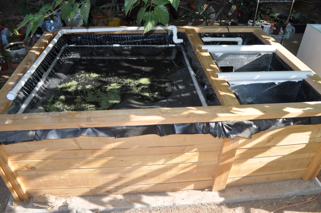
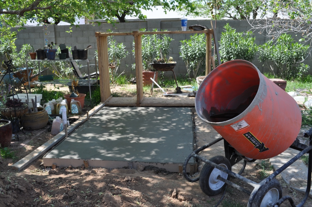
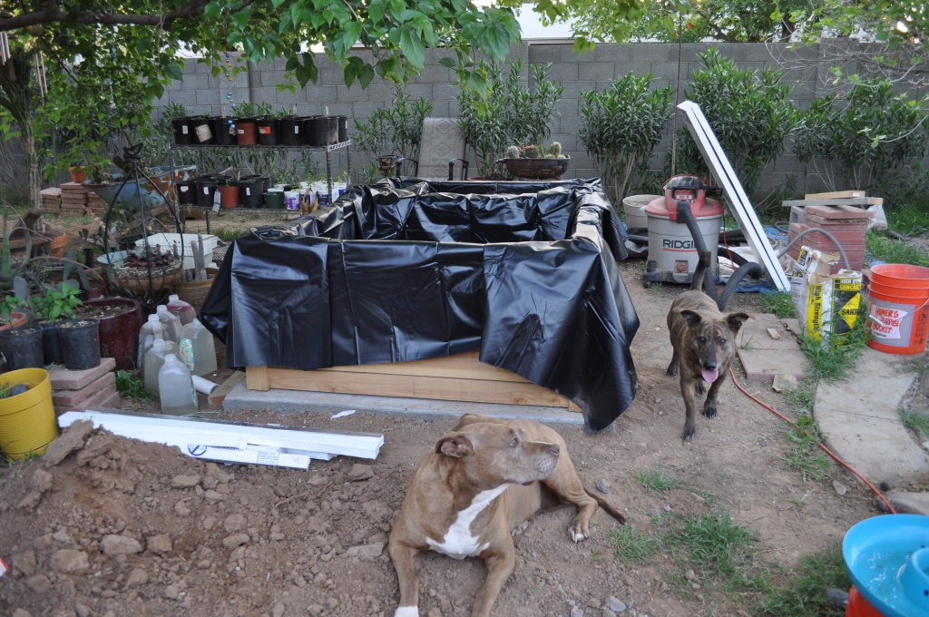
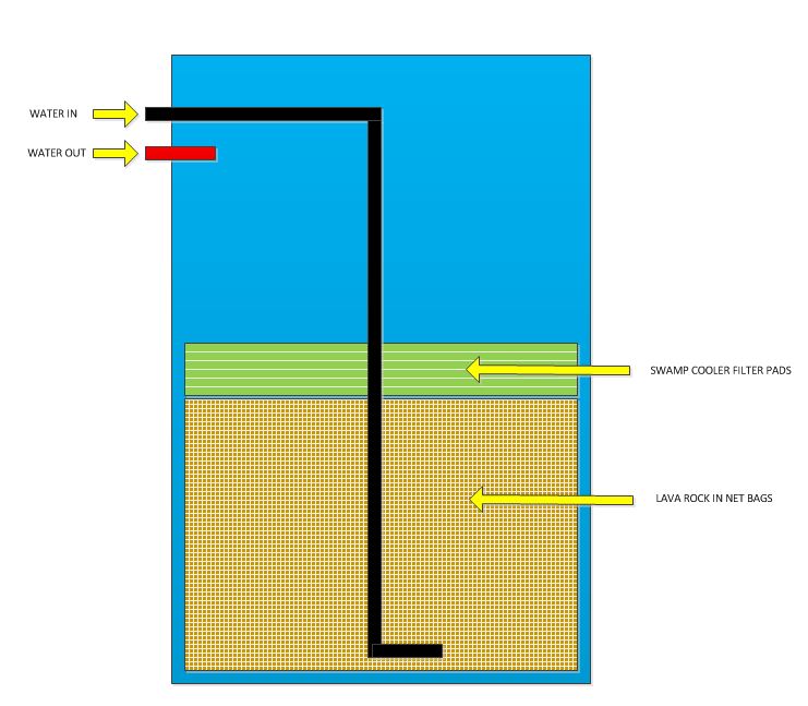
The Box Tank is, so far, our largest DIY tank. The main compartment holds approximately 200 gallons, the filter section has a 100 gallon capacity. It is configured the same way as The Refrigerator – the main compartment overflows into the filter section.
The Box Tank as of June 2013
As of March 2014, it is still a work in progress as I refine what I want to accomplish with it and also make some design changes along the way. Some are cosmetic, others are operational, such as a modification to the solids filtration section – will be posted later. Since this picture is almost a year old, I have added another two top layers of wood, added thin foam insulation to the outside and sheathed it completely with concrete siding designed to be used around the house. I have also made a few changes to the electrical system which I will add photos of later.
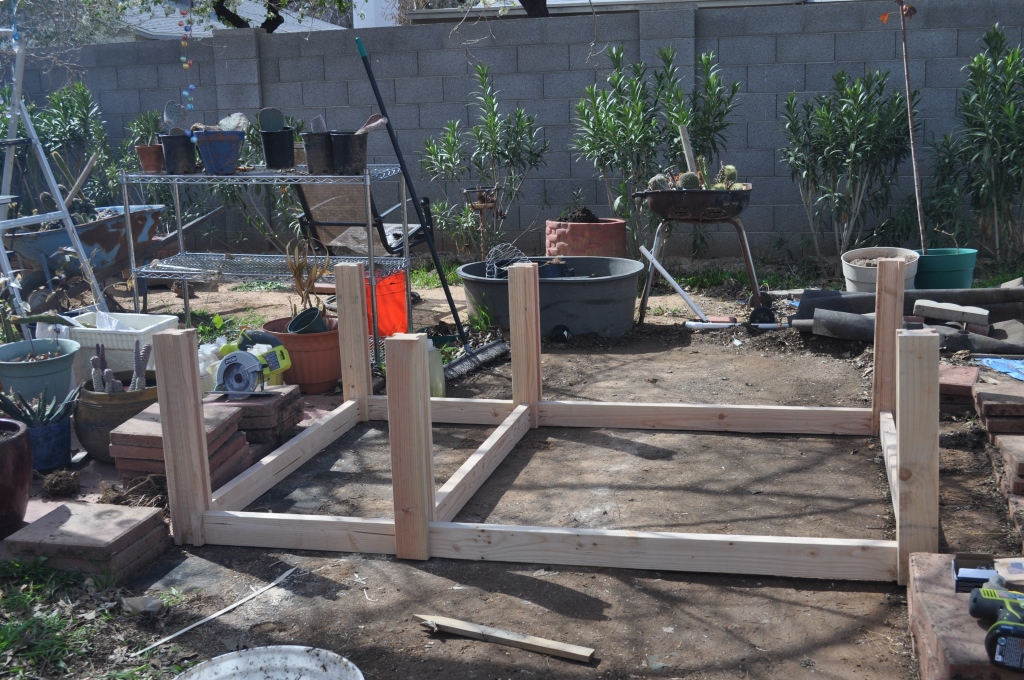
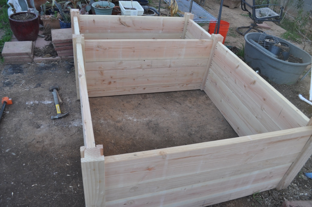
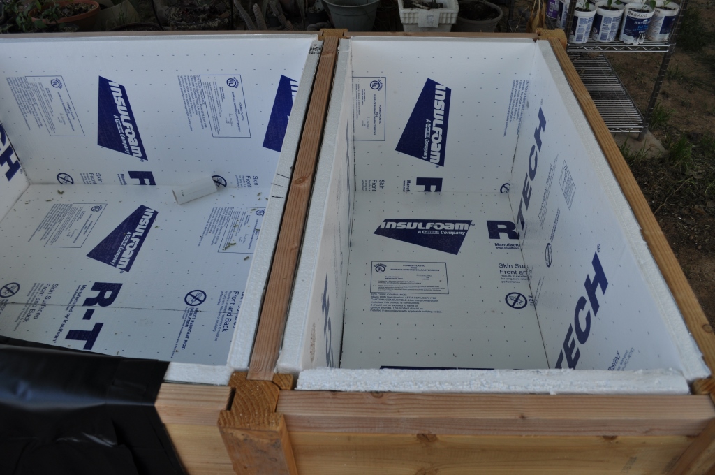
The Box Tank is probably the most costly aquaponics project to date as far as budget goes. I’ll post the estimated cost somewhere in this entry, but right now, I’m not sure how much the final number is. It will probably be in the parts list when that is completed. The Box Tank is about 5′ x 7′ x 3′ high and sits on top of a poured concrete pad that extends a few inches more on all four sides. Inside dimensions are 4’x4’x2’high for the main compartment and 4’x2’x2′ high for the filtration section. The framework consists of six 4×4 posts locked together with stacked 2×12’s and 2×6’s as the walls (pictures of the construction coming soon). Each post is rabbeted (slotted) so the lumber slide in to them, giving the structure its strength. Each 2×10 is screwed in place using pocket holes (similar to kitchen cabinet construction) using galvanized deck screws. The inside layer – bottom and sides are sheeted with 1.5″ thick Styrofoam insulation. The Box Tank is home to most of our Tilapia (a mix of Blue Niles and Red Hawaiians), who have now been with us for about 18 months. The tank population is about 15 fish, varying sizes from 8 ounces to 20 ounces. Yes, they are having babies! All total so far surviving about 13, so a majority are casualties. We have seven (1″ – 4″) in a separate pond and six are small minnow size (< 1″) in the filter section!
Parts List – tank frame (work in progress)Lumber (cut list) – you can purchase what lengths best suit your convenience. I have a vehicle that has a relatively small transport capacity and had some lumber cut to size at the store. Remember, measure twice, cut once!
Design note: As you can see from the pictures, I staggered the 2×6 and 2×12 lumber, mostly for cosmetic reasons. This is presented as a guideline and should give you the ability to cost out the project according to availability of materials at your location. Also, since this is the first tank of this type we constructed, some of the additions were made after the original planning stages.
Styrofoam –
3 ea. – 4’x8’x1.5″ sheets cut into the following sections Main compartment
1 ea. 4’x4’x1.5″ (bottom)
4 ea. 4’x2’x1.5″ (sides) Filter compartment
3 ea. 4’x2’x1.5″ (bottom and 2 sides)
2 ea. 2’x2’x1.5″ (2 sides) Note: These sheets may have to be trimmed slightly to fit. Construction adhesive can be used to stick the Styrofoam to the wood sides, however, the weight of the water against the liner should be more than adequate to hold them in place.
Construction process
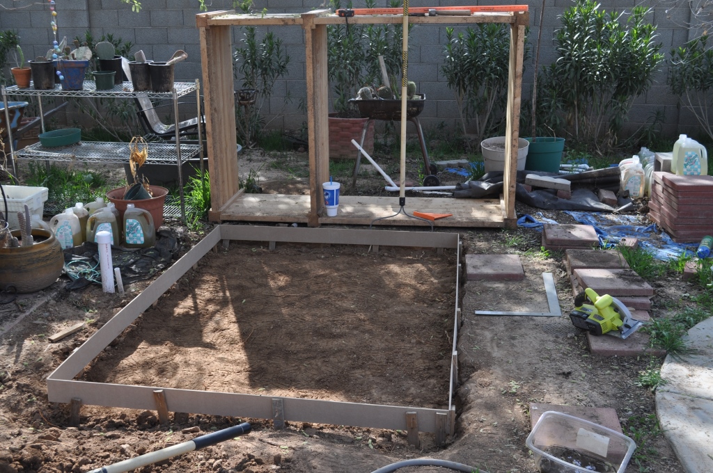
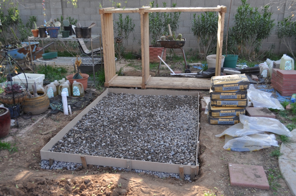
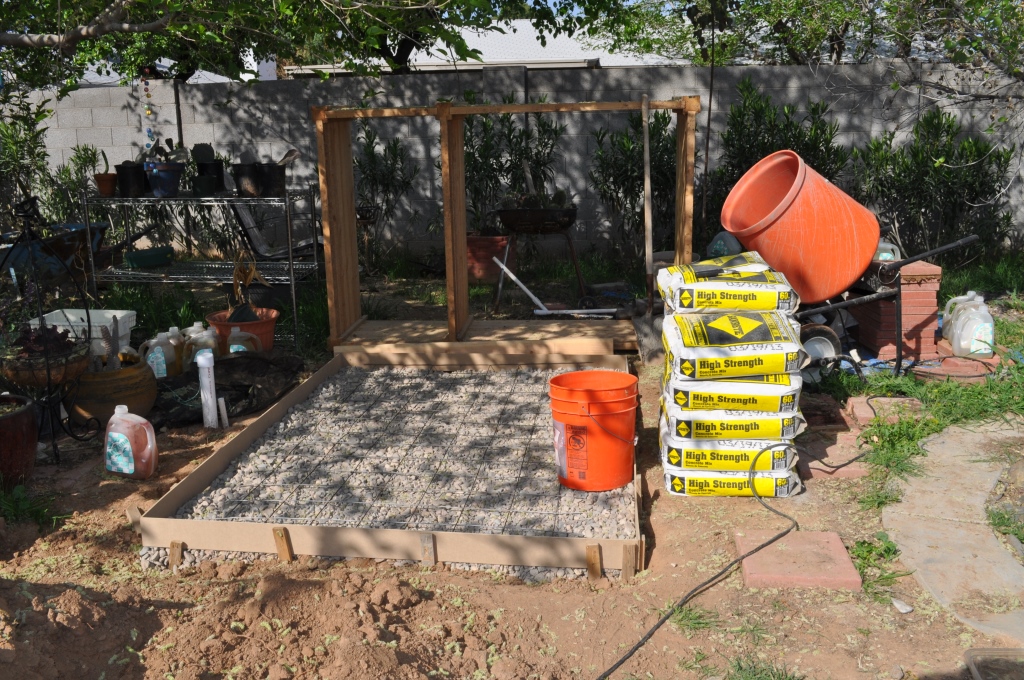
Lay concrete foundation (optional, but highly recommended – we were originally going to put it on leveled ground, but thought it would be better on a pad in case it rained hard. We didn’t really want the lumber to be directly on the dirt.
Form in placeRock sublayerWire mesh for strengthPad poured!!
Cut all lumber to size
Cut rabbets in 4×4 posts – just did multiple passes on my table saw. You can use a dado blade or router.
Drill pocket holes in all lumber used for the walls (this part is optional – use what ever joinery you are happy with). I purchased a Kreg Pocket Hole jig from Rockler and have used it in many projects over the years. I highly recommend getting one if you don’t have one.
Screw framework together.
Six posts and first layerAll the lumber in place
Cut and place 1.5″ Styrofoam insulation in bottom and sides of both main compartment and filter compartment.
Sheets of insulation cut to fit inside frame. It’s really hot in Phoenix, so I want to give fishes the best protection without having to purchase a chiller (mucho expensive!!)
Drill plumbing pass through holes in foam and walls. I set up two drains – a 2″ main drain and a 1″ drain slightly lower. The 1″ drain is designed to be used to attach a siphon hose for solids removal at the bottom of the main compartment. I also ran 1 additional 1″ pass through for the spray/aeration plumbing, so there are a total of three pass through holes. As an afterthought, the spray/aeration could run on top of the first cap (layer 1).
Fit liner for main compartment – fold as required.
Fit liner into main compartment and filter compartment. I was able to purchase 1 large liner and cut it into the correct sizes needed for both. Be very careful when you cut, you only have one chance.
Cut holes in the liner for the filter and pump pass-through plumbing.
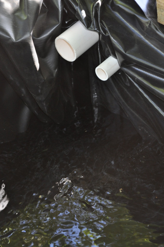
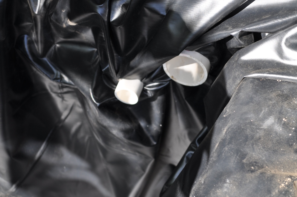
Fit PVC pipes for pass-through drains – secure with the appropriate pipe clamps and use waterproof silicone as a bit of insurance.
Do the same as above for the filter compartment.
Filter side pass through pipes in place.Tank side drain pass throughs.Tank side pump – water in from filter.Water test. Filling the filter and watching the overflow into the main compartment. As this is happening, I am checking all around the framework for possible leaks.Aeration assembly from pump in filter. The diagonal piece of PVC is there just for support until the upper layers to the framework are in place. Plumbing and water test working well! The 2″ pipe at the bottom of the tank pulls the overflow drain water from the bottom so there is a deep circulation of all water coming into the tank from the filter.Water drains from the main tank into the solid filter pads. I placed a large stone on top of the foam separator because it would not stay in place. Styro is EXTREMELY buoyant! No kidding!Framwork layer 1. 2″ PVC pipes now hold the Styrofoam separators in place. Inside the tank I made a square frame with mosquito netting attached to keep debris out of the tank and also to protect against predators (yes, we have a local heron that has dined on most of our goldfish and one tilapia).
DO NOT TRIM EXCESS LINER UNTIL AFTER A COMPLETE WATER FILL AND TEST!!! The weight of the water will push the liner into all possible cracks and crevices and may take more than you expect.
Attach layer 1 wood cap
Step back and admire your hard work, have a drink even.
I’m a happy camper!
Grab the garden hose or connect a water source and fill up about 1/3 capacity. Wait for at least 1 hour and check all around the base of your tank for obvious signs of water leakage. Once you are certain everything is happy, fill up the tank to capacity.
Complete your plumbing and connect the pump. Plug it in and keep the water going until you have 1/3 – 1/2 of the filter section filled with water. Let the pump run at least 24 hours and check occasionally for signs of water leakage. You are almost all the way done, last few steps is to complete it by adding filter pads, media bags and separation for water flow in the filter section.
The Filter Section
Solids filtering: I purchased a large roll of swamp cooler filter pad (light blue, looks like a big Scotch brite pad). I cut 3 – 2′ x 2′ sections and folded them in thirds to make a 9 layer solids filter. These get placed under the 1″ and 2″ drain pass-though pipes. I secured the pads in place by cutting a spare piece of Styrofoam to fit inside the filter. I cut a rectangular hole at the bottom of the foam approximately 12″ by 6″ to allow water flow. Since the foam sheet was so buoyant, I had to secure it by cutting a 2″ PVC pipe to extend across the filter section.
Biological media: I purchased 6 garment bags at WalMart for $1 each. I then put about 15-20 pounds of lava rock in each bag. If you fill these bags too much, they may break, so use your best judgment. Rinse the lava rock thoroughly before you place them in the water, as most bags of lava rock have lots of tiny bits of broken of rock and will cloud your water quickly.
Biological Filtering Editorial
Recently, I came across a YouTube from some guy who runs air through the biological media. He says the biological filtration happens as part of an aerobic reaction, that the little bacteria need a strong air supply to do their job well. This needs some verification, but if true, could result in a new filtration design. Unfortunately, air requires another device taking more power.
City Water and Chlorine – most municipalities in the US add chlorine to tap water to kill various nasties. Chlorine will kill your fish. Having maintained inside aquariums for many years, I typically add an anti-chlorine or chlorine-neutralizing chemical to any water I add to my tanks. When we get to this size tank, this can get expensive. I generally have to add 5-10 gallons a week to the box tank due to evaporation. I can only speak to my experience, however, as tap water is circulated and aerated, the Chlorine is ‘thrown off’. It out-gasses or gets released from the water. Some say you can leave a 5 gallon bucket of water exposed the air for 1 hour, some say overnight. Putting an aerator in your container will probably speed up the process. I have filled up 2 five gallon buckets of water straight from the hose and added it to my box tank with no noticeable effect on the fish. I think the chlorine gets so diluted when it is added to 200+ gallons of water (less than a 5% addition) that it is not an issue. Again, I cannot stress enough that this is something you need to verify for yourself – test the levels with a chemical test kit if necessary, to give you the comfort level you need. It’s not worth losing fish over.
OPTIONAL
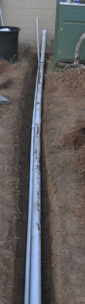
I decided during the planning stages that we would need an electrical outlet very close by as the system would need two pumps, a sensor unit and who knows what else? That is three items… so, I dug a trench and buried a length of 2″ PVC to act as an electrical conduit to the tank. I also thought it would be nice to extend pressurized city water to the tank, so along with the electrical conduit, I buried a 1″ PVC for water. As of today, the water is still not active, but I am looking forward to making it happen. On the electrical side, I put in two GFI outlets and they have worked marvelously. As it turned out, I needed more electrical as over the winter, I hung two aquarium heaters in the main compartment to keep things happy.
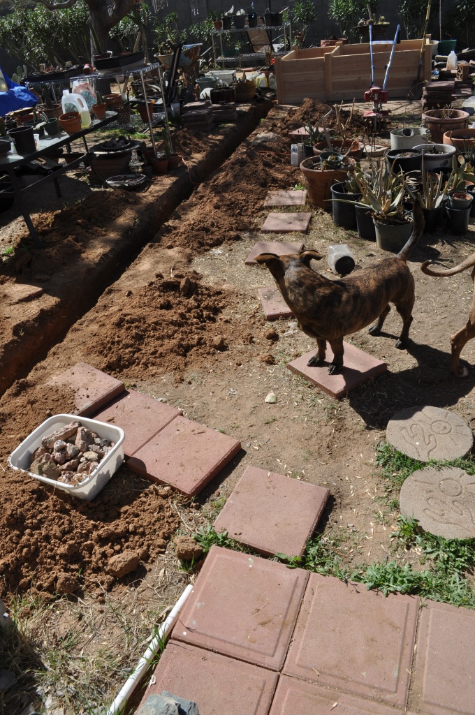
Canine Site Inspector JoJo checks out the trench (about 8″ deep) and wonders if he can do better, or perhaps, what a wonderful bone burial area this would be!Installed 2″ and 1″ conduit.
Conduits buried, capped and pull string in place. A pull string makes pulling the electrical and other wires through the conduit much much easier.
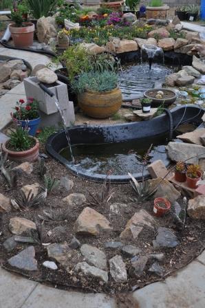
Our backyard ponds were our first step into outdoor aquaculture. The design philosophy behind it was to get a system going to see what was involved in keeping fish alive year round in an outdoor environment. Originally, we had planned on getting an above ground swimming pool. There were several available and we purchased a 10′ diameter one for just under $100.00. It had a 1000 gallon capacity. As we began to figure out the logistics, we realized that our dog JoJo might decide to take a dip possibly penetrating the soft floor with his claws. So, we backtracked on the pool idea and then came across two plastic pond shells for sale on Craig’s list. They didn’t have the holding capacity of the 10′ pool, but it would still be a good start.
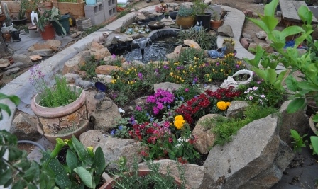
Ponds with rock garden and path.Ponds with rock garden and path – reverse view.Large Pond
Both ponds were 2 tier or level. The smaller one has one shelf that you would put an aquatic plant on, and the larger had two larger shelves. Our first idea was to bury each one up to the shelf level and then build up dirt to the edges, enclosing the area with cinder blocks.
Ponds with cinder block support
For a lot of logistical reasons, this idea just didn’t work out. We dug bigger holes and put the ponds in the ground all the way to the lip.
JoJo, canine site inspector, closely inspects for correct level
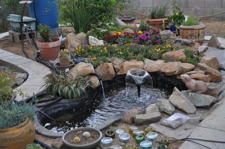
The ponds came with one filter. It was a commercial one that had a pump inside a media filled plastic box that sat in the pond. The pump inside the box fed a rectangular filter box that had an ultraviolet light chamber which overflowed into a tray with another pad to filter solids on top of a flow through filled with lava rock. This box would be positioned above the level of the pond so the cleaned/filtered water would then gravity flow back into the pond. The guy I bought it from said that it kept the big pond very clean. I had other ideas for a filter.
The Barrel Filter. I got this idea from a website I came across while looking to make inexpensive filters. If you get into this kind of stuff, you will find plenty of manufactured products to help you along the way. They are affordable for small scale ideas. If you want to get into aquaponics, you will not stay small scale for long, and the commercial products will kill your budget. Besides, I’m a DIY guy with a small budget, so I look to solutions outside of the commercial realm. I purchased a 55 gallon food grade barrel with a removable lid – I think it cost about $35. The reason I paid more to get a barrel with a lid is that it allowed me to do the internal plumbing and then seal it back up again easily. I drilled two holes near the top edge and put in 1″ PVC bulkhead fittings. I then put PVC inside the barrel going down to the bottom. This was where the water would come into the filtration system. The second hole acted as the overflow and return to the pond. I also put ball valves on each so I could perform maintenance and not have issues with water back-flowing into the pond. The pump to run the whole thing sits in the pond and is my usual 600 gallon per hour model. I like this configuration because it allows me to do maintenance on the pump without having to worry about opening up the barrel. Inside the barrel, the water passes through six lingerie bags filled with lava rock. Then the water passes through three layers of swamp cooler filter pads and finally gets to the overflow pipe.
Working diagram of the barrel filter
I wanted to run both ponds on this one filter, but quickly realized that the overflow rate would be very difficult to manage. On paper, it sounds fine. Two 600 gallon per hour pumps feeding 1 filter with an overflow back to each pond. The reality is, if one pump got clogged up while the other one didn’t, the difference in water flow would easily flood the other pond, creating a disaster. So the barrel filter became the filter for the large pond and I would have to figure out something else for the smaller pond. In the beginning, I used the filter I got with the original ponds, but eventually, I made a 5 gallon bucket version of the one above feeding it with a 260 gallon per hour pump.
Later on in the year as it got cold, I wrapped the barrel in fiberglass insulation (spare from another project) and put a tarp over it for protection from the weather.
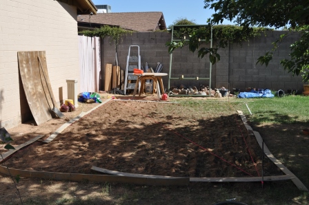
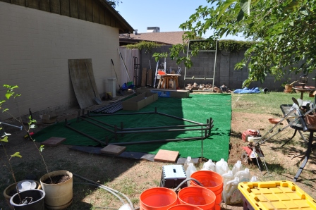
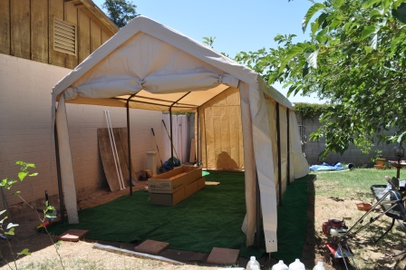
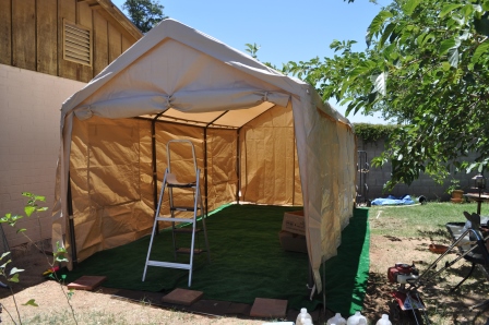
I spent a bit of time trying to figure out the best way to lay out my aquaponics plan. Debbi and I went through many designs for the back yard using a scale layout in Visio to plot our existing trees, the walls, etc. Each one seemed to have a fair amount of startup costs and permanence. What I mean by permanence is the project involved setting or anchoring something in the ground that would stay with the house for a long time. One day, while I was shopping in Costco, I saw a 10′ X 20′ carport tent for around $250.00. After some discussion and looking at our layouts, this seemed to be the best fit. The main feature I liked about this tent was the framework – it looked like it had 1.5″ steel pipe throughout. The sides and canopy were made of fairly good weather resistant materials and had a few openings for windows and other access.
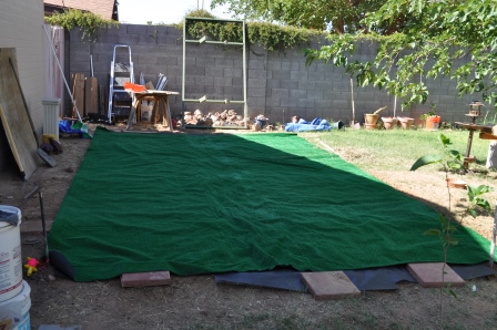
We began by preparing the ground, leveling it out and then laying down artificial turf carpet. We decided against pouring a concrete pad, again, we weren’t sure if we wanted it to be that permanent.
Ground preparationLaying down the carpet
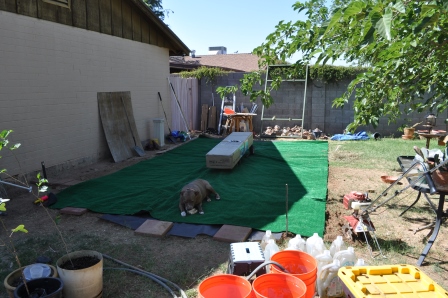
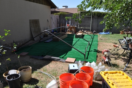
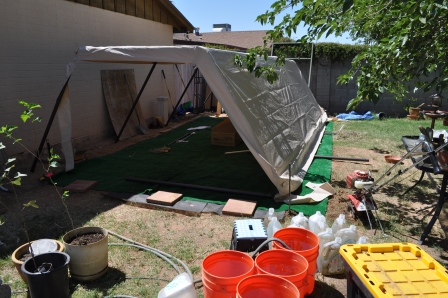
Once the ground was leveled and the carpet laid out, construction of the frame began. I wanted to do this as a one man job, just to see if it could be done. It took me about three hours to put together.
Laying out the box. Mason, my daughter’s pit-bull inspects and supervises the build – 9:11amRoof trusses assembledCross beams in placeLeft side in pace and canopy positionedRight side and back panel in placeAll done! 11:57 AM
As of this writing, the tent has been in place almost two years. I have had to replace the top canopy last year (cost of about $75.00). The rear drop down (the side facing the grey concrete block wall with ivy on it) has completely disintegrated being exposed to the sun the most. The replacement canopy (UV rated mind you), has also developed holes and weak spots. The only thing that makes me not regret this purchase is the framework, which is still solid and the best feature of this product.
The next canopy replacement will not be with a fabric-like material like the one that is in place today. I will be planning on putting 2X4 cross beams in place and mounting corrugated fiberglass roofing to the beams. I will probably do the same on the end, as it will make the structure more weather-proof. I am still undecided as of yet as to the color of the corrugation as a clear one is available.
All things being said, it has made a reasonably good shelter for my projects and lots of other stuff. Going forward, if plans are what plans are, we will probably pour a concrete pad, re-enforce the roof and replace it with corrugated fiberglass roofing. If we go this route, I expect it will be done late in the year (2014).
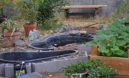
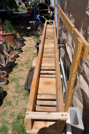
The Trough was a project born out of trial and error. When I started the aquaponics project two years ago, my vision was to have it all in a carport tent. It didn’t quite go as I planned, but I learned a tremendous amount of what to do and what not to do. As far as the plants were concerned, I found out that they all leaned toward the opening of the tent, and since my grow beds could not be move… well, you get the idea. I also found out that some plants can grow really big and overshadow the smaller ones. The winter of 2012/2013 was a tough one for us here. Five days of below freezing for 12 hours a day. It wiped out every plant in my barrels except for the mint.
The Trough project actually is two parts, one part is the trough, the other is the tank.
The Trough next to my 10’X20′ tent”Sump/fish tank box”
Design Requirements
1. Need the ability to move plants quickly if needed – move them indoors if necessary to avoid freezing temperatures.
2. Also need to be able to move plant containers apart to accommodate for large growth. Plants will get plenty of water, must have light also.
3. Attach the plant containers to a water source that also served as a home for fish to generate the required nutrients for the plants.
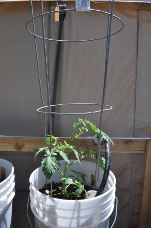
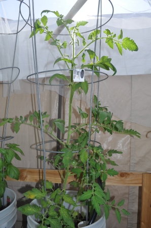
4. Capacity needed to be six plants of good size – my goal was for the starters to be tomato plants.
5. Buckets need to be food-grade. I didn’t want plants I would be eating from be growing in plastic made from questionable materials. Some plastic is food grade, some is not.
6. Controllable water flow to each bucket should be easily adjustable.
7. Size of container needs to be large enough to accommodate the plant without having to continually transplant to larger container.
8. Each bucket should have the capacity to be electronically monitored (water level).
9. Electronic/wireless water chemistry monitoring.
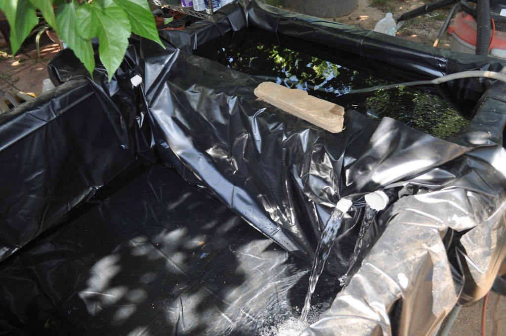
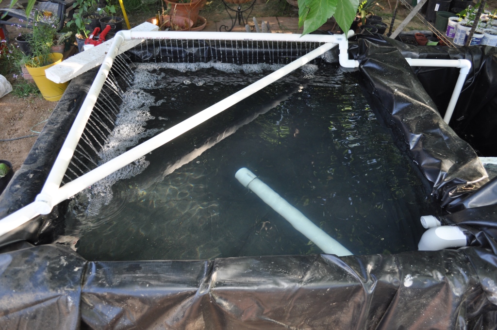
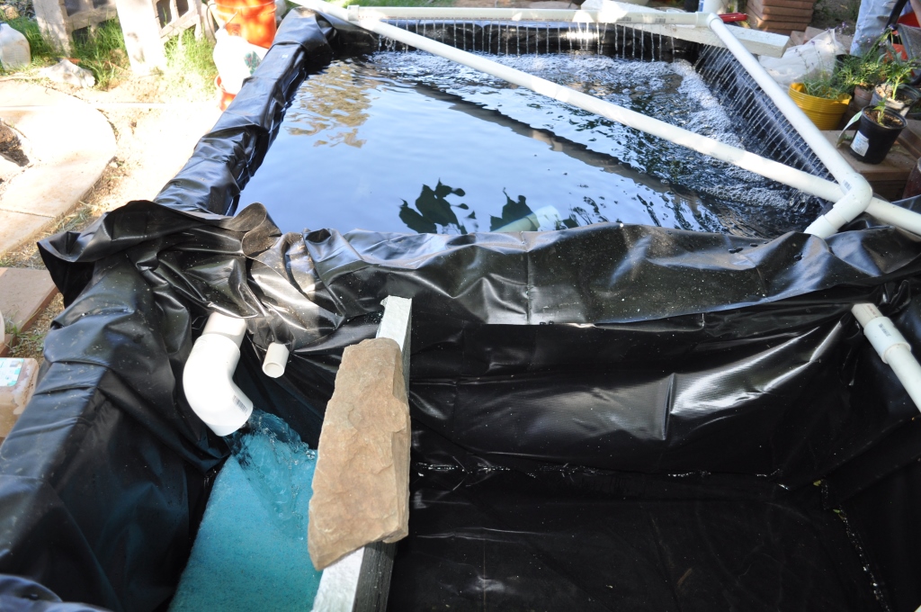
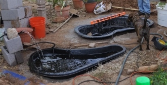
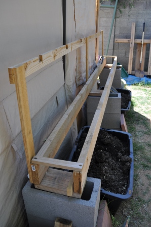
The Trough frame: version 1″The Trough frame: version 2 – sans liner”The Trough frame: version 2 – with liner, supporting frame and return drain”
During it’s stay during 2013 next to the tent, the trough went through several design changes. The first one was the water return system. As you can see in the pictures above, I have a 2″ PVC pipe under the buckets to return the water to the tank. My initial water tests proved this pipe did not have the capacity to handle the amount of water flow draining from the buckets, so the inside of the trough was re-enforced and lined with some pond liner material I had spare.
Inside my tent, I had three barrels configured with bell siphons. These took quite a bit of fine tuning, but once done, they required very little adjustments. My idea was to do the same with the buckets. I also controlled the water flow into the barrels with PVC ball valves. These valves turned out to be very difficult to adjust smoothly.
So, I made a test concept bucket using a Home Depot bucket to see if things worked correctly – and they did. However, I did not do this bucket test with planting medium – what is the saying about hind-sight? 20/20? Mark this one as the second design change. Once I had filled the bucket with expanded clay pellets, the water capacity went from 4 gallons to 2 gallons. This didn’t surprise me, however, the bell siphon operation changed so much, it became almost impossible to adjust, even with brass faucets. Sometime down the road, I will post on bell-siphon and designs involving them. Anyway, I moved away from using a bell siphon in the buckets to a continuous water flow model. I removed the faucets from the feed tube and replaced them with straight barb fittings and black tubing feeding the buckets directly.
Plant growth was really good. It only took six weeks for the tomato plants I got to jump up almost past the top of the frame. It seemed each week we had wonderful growth.
Heat Master hybrid – April 21, 2013″Heat Master hybrid – May 19, 2013″
Then the summer months took their toll. 110 degrees each day coupled with no shade for over 8 hours. My plants fainted in the blistering exposure. I ended up pulling the plug on the pump in mid-June.
I was crushed, despondent even. However, my wife Debbi encouraged me to push on. We would figure out a new plan. Clearly, the trough had to be moved to a better spot, so next year (2014), we would start again under the shade of our large Mulberry tree. Epic failure, no, not at all – but a very good learning lesson that in Arizona, you can never discount the sun, no matter how much water you throw at something.
See the post on ‘The Refrigerator’ that shows the resurrection of the system. As of this writing, it is mid-March, 2014. Growing season is in full swing, summer time will be the full test.
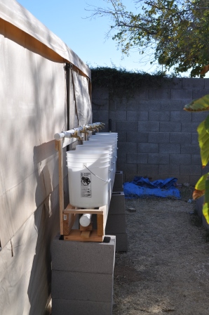
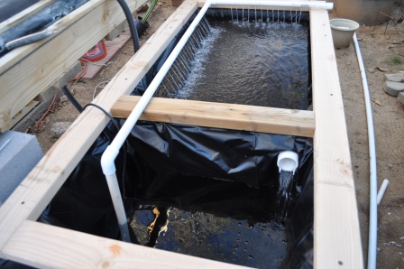
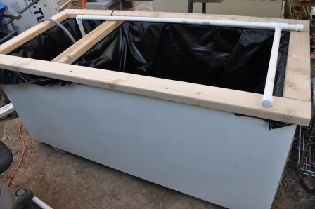
We’ll start off with our latest project – re-tasking an old refrigerator to use as a fish tank and water source for my plants. It took several weekends to put together, mostly due to logistics and getting things right the first time (hopefully). As of this writing, it’s not completely finished, but it is completely operational. I’m not sure I have many projects that I could consider ‘completely finished’.
Concept almost completed – water test operational”
Summary
The Refrigerator is a project that is part of an overall bigger project that includes ‘The Trough’. We had an old refrigerator that stopped working and decided to put it to use. I couldn’t haul it off and the pickup guys only wanted working appliances… go figure. So my wife said… let’s put fish in it! My heart sank… I had other plans and just didn’t want to go there. However, I am really glad I listened because this project has turned out GREAT!
Design Concept
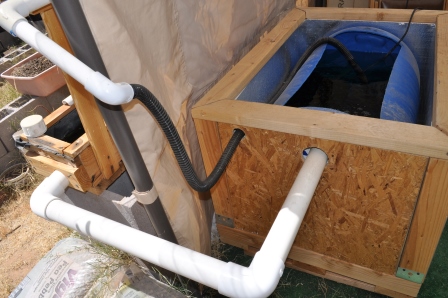
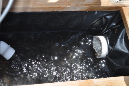
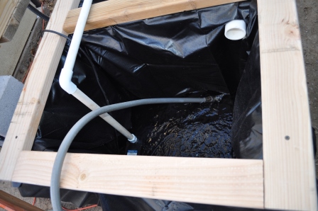
The design for this tank is to have the large compartment for fish with a 2″ PVC overflow drain into the small compartment which acts as a sump. In the sump, there are two 600/gph pumps, one pushes water back into the main compartment through a 3/4″ pvc pipe drilled with holes for aeration and the second pushes water through a 1″ flex pipe to six buckets with plants. We’ll cover the trough design in another entry. The buckets drain into a liner filled trough which then drains back into the sump. The expanded clay pebbles in the buckets act as filtration media for the fish waste. The main consideration I like about this design is the compartment holding the fish will always stay at the same water level, no matter what the level is in the sump, barring a catastrophic leak – hence, the importance of doing a plumbing and water check before adding your fish.
We started off with a junk refrigerator that was stripped of all mechanical items, such as the compressor, tubing and internal shelves. Essentially, just the shell. One of the reasons I really like this approach is we have a great starting point – a strong, insulated box with two compartments. We leveled the ground, put down three concrete landscape blocks and set the fridge on them. Calculating the liner size, I found that I needed to get 2 each 7’x10′ liners from the local box store. They cost about $35.00 each. I didn’t want to mail order custom sizes as I wanted to get the project underway quickly. I did a calculation to see if I could have cut one larger liner in two pieces, but the numbers didn’t work out. If you are doing this yourself, you will need to check it out to see if it is cheaper. The pumps are 600/gph fountain pumps bought at Harbor Freight. Using the 25% discount coupons I have, they weighed in at $30.00 each. I had the PVC laying around from other projects, but needed two more 2″ pipe clamps for the compartment overflow drain. All together, I think I invested about $150.00 in this project. What makes me happy though, is the pumps were already purchased last year.
Parts
1 used refrigerator
2 pond liners, sized to fit
1 pump (recommend 600+ gallons per hour)
1ea 10′ x 3/4″ PVC schedule 40 pipe
1ea. 3/4″ threaded PVC male (threaded) to female 3/4″ slip fitting (screws into pump
1ea. 3/4 PVC elbow
1ea. 3/4″ PVC tee
2ea. 3/4″ PVC caps
1ea. 2″ x 8″ PVC pipe
2ea. pipe clamp for 2″ pipe – better get one that opens to at least 2.5″
3ea. 2″x4″x8′ lumber for top frame (1st layer)
Construction
Step 1: start off by stripping everything out of the refrigerator that won’t be needed. Check for anything inside that may poke through the liner. Don’t forget that water weighs approximately 8 pounds a gallon, so if your fridge can hold 100 gallons, that’s 800 pounds of water pressing down on the liner against anything in the compartment.
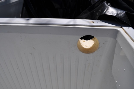
Step 2: Drill a 2″ hole from the freezer section to the main section. Make it fairly high up as this hole will be the highest point you will have water in the main compartment. The inside of my fridge was molded plastic with solid foam core. I had to drill from one side and then the other. Use a long drill bit to make your pilot hole from one side to the other and use that hole to line up your hole saw. Use what ever you think will work, however, I don’t recommend a paddle bit. I bit the bullet some time ago and purchased a Milwaukee chuck that allows me to put almost any size hole saw onto it.
Hole drilled for overflow – 2″
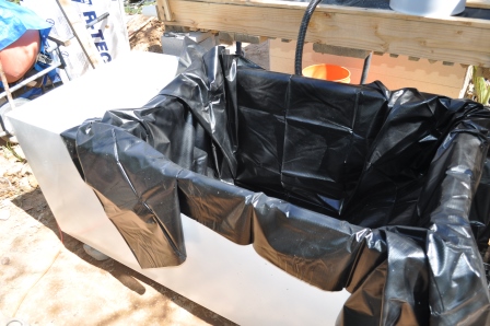
Step 3: fit the first liner in the main compartment. It’s a flat sheet going into a three dimensional hole, so you will have to fold it to fit inside, just like wrapping a present but in reverse. Some people like to fill it with a bit of water to make sure they don’t get surprises.
First liner placement
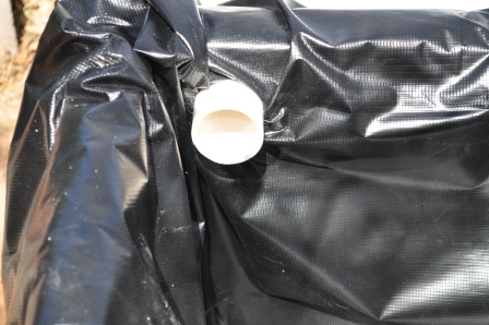
Step 4: the scary part – cutting the pass through hole in your liner. Perhaps I will write a blog just for this part, but I’m not there yet. I cut a hole about 1 – 1/2″ for a 2″ pipe pass through. Don’t take this measurement as gospel. Your liner may be different and stretch differently. I coated the 2″ PVC pipe with clear silicone sealer. I pushed and cajoled the pipe through the smaller hole in the liner. I then tightened the pipe clamp on over the liner. Just to be sure, I coated the pipe clamp with silicone also. Take your time with this or you will be buying another liner.
2″ pipe through the linerPipe clamp detail – before adding extra silicone
Step 5: fit the second liner in the freezer section. Line it up carefully with the 2″ pipe coming through from the main compartment. Make a small hole in this liner. Be sure you have the pipe clamp on the pipe before you push the liner over the end of the pipe. Once you have the 2″ pipe through, you will have to work hard to get everything lined up nicely. Folks, this doesn’t have to be perfect. The overflow side should NEVER have water coming close to it.
Note: You should NOT trim any excess pond liner material at this time. I did and it was a close fit. Wait until you have filled it completely with water before putting the knife or scissors to your excess liner.
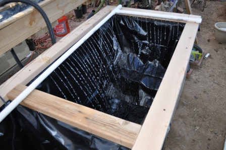
Step 6: Attach the threaded fitting to your pump. Cut the 3/4″ PVC into lengths to come out of the bottom of the freezer/sump section to the first elbow. Be sure to take into account the thickness of the wood you are using to frame the top.
The pump is in the water with the pipe attachedThe spray section is self supporting
Note: The wood frame is not just for decoration, it keeps the liner firmly in place.
Step 7: Cut another piece of 3/4″ PVC that will go from the elbow, across the dividing partition and most of the way across the main section. I can’t give you dimensions here because your fridge may be smaller or bigger than mine. Attach the tee PVC onto the end and add another piece of PVC to reach the far side. Put a cap on that end. Put one final piece of PVC into the remaining tee and extend it across the fridge frame to the opposite side. Cap the open end with another PVC plug.
Note: I dry fit all the parts. I am even running water at full pressure through the pipes without any leaks. It’s a good idea to make sure everything is set up correctly before you commit it with PVC glue. The glue sets in seconds and is most unforgiving if you mess up.
Step 8: drill a series of holes in the pipe pointing down at the water. I have them at about 1″ spacing. Don’t get angle of squirt too close to the edges or your spray will end up drenching the wooden frame. In fact, after I had run water for a day, I discovered that I needed to adjust the angle that the jets were hitting the water. Since everything was still in dry fit stage, this was very easy to do.
Step 9: water test!! Grab the garden hose and start filling the sump. Once you are about 1/3 to 1/2 way full, plug the pump in and let it fill the main compartment. If you are really cautious, let the compartments fill about 4″ – 5″ and inspect the bottom of the fridge for leaks.
Filling the main compartmentMain compartment is full and spray angle looks good so far
Step 10: finish filling the fridge until the main compartment starts overflowing through the 2″ pipe into the sump. Continue filling the sump until it’s at least half way full. Let the system run for at least 24 hours. The water will be ready for fish as all the chlorine usually added to city water will have off-gassed. In fact, it will be fine after about 1 hour. I like to run it for a day just to test the system.
Step 11: once you are satisfied everything is running nicely, cut your 2×4 lumber to size and make a frame out of it. I have a Kreg pocket-hole jig to put the frame together, but you can make it any way you like. I stink making miter cuts. One of these days I will get a nice Miter saw. Screw the frame into the fridge – you will probably have to drill pilot holes. I used 3″ drywall screws to mount it on the frame.
Step 12: finally, when you are happy and everything is running right, use a knife or scissors and trim back the excess pond liner. See how tight everything is when you have water? Best to have slop until you are finished.
Missing fish report!! I know it sounds crazy, but in our main garden pond, we had four goldfish on Sunday, March 9. On Monday, we have only one and it is completely freaked out swimming around. My wife saw a blue heron a few months ago, so we can only assume it came back for another snack. We had a partial cover over this pond and floated corked wine bottles in hopes this would cause any predator to not snag our fish. We’re very sad as these guys were about three years old and had grown from one inch to about four inches. Some of them had very nice looking tails. I hope that bird gets indigestion!
Monday night, I went by Petco to grab six feeder goldfish and six ruby minnows for the Refrigerator tank. We also moved our remaining goldfish from the pond. The Refrigerator has a large piece of insulating foam on the top of it until the frame is completed and has a hinged lid. We are planning on using a piece of Plexiglas in a wood frame.
So, as of right now, fish are happy, but small. The gal at Petco said the minnows could grow to 24″ – we’ll see.
Next steps…
1. Build up the Framework to enclose the pipework
2. Add a hinged lid (with Plexiglas)
3. Pretty up the sides with wood panels made from scrap
4. Paint inside of frame with some water resistant paint or sealer